Design and Manufacturing according to ATEX Standard
Introduction
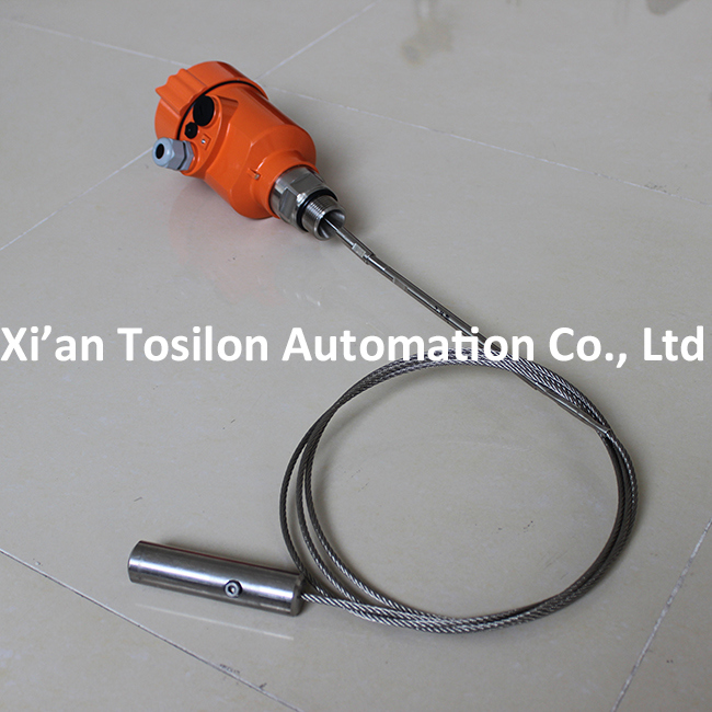
Guided wave radar meter is a gauge based on time stroke principle, the radar wave is running at speed of light, the running time can be converted to material level signal through electric components.
The sensor emit high frequency impulse and transmit along the cable, when impulse meets the material surface, it reflects back and is received by receiver inside the gauge, and converts the distance signal to material level signal.
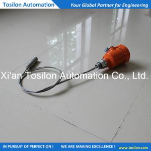
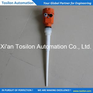
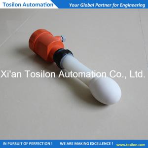
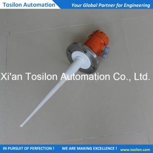
Outline Structure
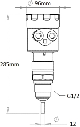
Technical Data (For details, please contact Tosilon)

| Working frequency | 100MHZ-1.8GHZ | |
| Measuring range | Cable Type | Rod / co-axial type |
| 0-30m | 0-6m | |
| Repeatability | ±3mm | |
| Resolution | 1 mm | |
| Sampling | wave echo sampling 55 times/s | |
| Response Speed | >0.2S (depends on concrete application status) | |
| Output | 4-20mA | |
| Precision | <0.1% | |
| Communication Interface | HART Communication Protocol | |
| Process Connection | G1-1/2, Flange 2″,3″,4″,6″ | |
| Process Pressure | -1-40bar | |
| Power Supply | 24VDC (±10%) | |
| Ripple Voltage | 1Vpp | |
| Power Consumption | Max. 22.5mA | |
| Environment Conditions (Degrees Celsius) | -40~+70 / -40~+250 / -40~+400 | |
| Shell Safety Grade | IP68 | |
| Anti-explosion Grade | EXiaIICT6 | |
| 2-wire | One two-core shield cable is used for instrument power supply and signal output | |
| Cable Entry | two M20×1.5(cable diameter 5--9mm) |
 China
China