Measurement Principles
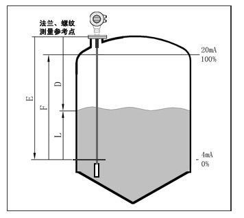
The guided-wave radar level meter is a measuring meter basing on time-stroke principle and the radar wave runs at the speed of light. The running time can be converted to level signal through electronic components. The distance between measurement reference point and material surface, the probe transmits high-frequency impulse which transmits along the cable, and when the impulse is reflected after encountering the material surface, it will be received by the receiver in the meter, and the time signal will be converted to level signal.

Input
The reflected pulse signal transmits along the cable to the electronic circuit part of the meter, and the micro-processor will process the signal, identify the echo wave of microwave impulse reflected on the material surface.The correct echo wave signal will be identified by the intelligent software, and the distance to material level D is in direct proportion to time-stroke T of impulse.
D=C×T/2
Where, C indicates velocity of light.
Because the distance in empty tank E is known, the material level L is:
L=E-D
Output
By configuring empty tank height E (=Zero), full tank height F (=full range) and some application parameters. The application parameters will adapt the meters to the measurement environment automatically..
| Application | Solid power |
| Measuring range | 30 m |
| Process connection | Thread, flange |
| Thread, flange | -40-250 degree |
| Process pressure | -1.0-40bar |
| Precision | 5mm |
| Frequency range | 500MHz-1.8GHz |
| Anti-explosion | Exib IIC T6 Gb/ Exd IIC T6 Gb |
| Signal output | 4 ... 20mA/HART (two-wire) |
| Power supply | DV24V(two-wire) DC24V / AC220V(four-wire) |


 China
China