Working principle
01. By means of Absorbing the calcium and magnesium ions in water with resin, since the hardness of water is mainly composed of calcium and magnesium, in general, we adopt cation exchange resin (softener), replace Ca2+, Mg2+ (main ingredients for scale) in water, as the increase of Ca2+ and Mg2+ in resin, removing performance on Ca2+, Mg2+ of resin will gradually reduce.
02. When the resin has absorbed a certain amount of calcium and magnesium ions, it must be regenerated, the regeneration process is that flush resin layer with the salt water in salt box, replace hardness ion out of the resin again, and discharged from the tank with waste liquid of regeneration, then resin resumed the function of softening and exchanging.
03. The principle of sodium ion exchange and softening treatment is to exchange cation in the raw water with resin, hardness constituents Ca2+and Mg2+ in water exchange Na+ in resin, thus absorb the Ca2+and Mg2+ to make the water to be softened.
2RNa + Ca2+ = R2Ca + 2Na+
2RNa + Mg2+ = R2Mg + 2Na+
After the water treated by sodium ion exchanger, the Ca+ and Mg+ were superseded by Na +.
Application scope of softener
Mainly used in industry and civil water softening preparation, such as Boiler feed water make-up water, air conditioning system make up water, heat exchanger, power plant, chemical, textile, printing and dyeing, bio-pharmaceutical, Electronic system and water pretreatment.
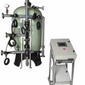
Control mode of fully automatic water softener
(1) Single tank time type: It adopts microcomputer to control the time, when operation of the equipment reaches setting time, it will automatically enter the regeneration condition, which can be regenerated for once a day or once for some day.
(2) Single tank flow type: It adopts control of turbine flow or electronic flow sensor, when the yield of softener reaches preset flow it will automatically enter the regeneration condition, which can be recycled many times every day.
(3) Double tanks flow type: Which could be divided into one running-one alternating, and simultaneous running and separately regeneration.
(4) One running and the other alternation type: One tank is running while the other is alternating, when water yield of operating tank reaches the preset flow rate, it will enter the regeneration stage, meanwhile, the other tank will enter the working state, these two tanks work and regenerate alternatively to realize continuous water supplying of 24 hours.
(5) Simultaneous running and separately regeneration type: Two cans running simultaneously, when the flow rate reaches the setting rate, one tank (can) will regenerate and the other tank will output water continuously, when the first regeneration tank finish the regeneration it will enter the working stage, the other one will enter regeneration stage, these two cans finish regeneration and enter working state simultaneously.
| Hardness of raw water | Less than 8mmol/L | Power supply | 220V/50HZ |
| Hardness of effluent | Less than 0.03mmol/L | Control mode | flow rate type, time type |
| Inlet water pressure | 0.2to 0.4Mpa | Resin | 001×7strong acidic cation-exchange |
| Free chlorine | Less than 0.3mg/L | Working ambient temperature | 5-50Centigrade |
| Suspended solid | Less than 0.5mg/L | System water temperature | 5-45Centigrade |
| Iron content | Less than 0.3mg/L | Relative humidity | Less than 95%(25Centigrade) |
| Category | Model | Recommended water yield (M³/h) | Tank size Diameter *Height(mm) | Salt box (L) | Amount of resin(KG) |
| Single-valve and single-tank | YL-I-0.5 | 0.5 | 200×900 | 25 | 20 |
| YL-I-1 | 1 | 250×1400 | 60 | 40 | |
| YL-I-2 | 2 | 300×1400 | 200 | 60 | |
| YL-I-3 | 3 | 350×1400 | 100 | 80 | |
| YL-I-4 | 4 | 400×1650 | 200 | 120 | |
| YL-I-5 | 5 | 500×1750 | 300 | 180 | |
| YL-I-6 | 6 | 300×1900 | 350 | 240 | |
| YL-I-10 | 8-10 | 750×1900 | 500 | 360 | |
| YL-I-18 | 42-18 | 900×1900 | 800 | 520 | |
| YL-I-25 | 18-25 | 1000×2200 | 1000 | 720 | |
| YL-I-35 | 25-30 | 1200×2400 | 1500 | 1000 | |
| YL-I-50 | 35-50 | 1500×2500 | 2000 | 6400 | |
| Dual-valve and dual-tank (simultaneous operation and respective regeneration) | YL-II-36 | 24-36 | 900×1900 | 800 | 1040 |
| YL-II-50 | 36-50 | 1000×2200 | 1000 | 1440 | |
| YL-II-70 | 50-70 | 1200×2400 | 1500 | 2000 | |
| YL-II-100 | 70-100 | 1500×2500 | 2000 | 3200 | |
| Dual-valve and dual-tank(One for use and the other for standby) | YL-II-1 | 1 | 250×1400 | 60 | 80 |
| YL-II-2 | 2 | 300×1400 | 100 | 120 | |
| YL-II-3 | 3 | 350×1400 | 100 | 160 | |
| YL-II-4 | 4 | 400×1650 | 200 | 240 | |
| YL-II-5 | 5 | 500×1750 | 300 | 360 | |
| YL-II-6 | 6 | 600×1900 | 350 | 480 | |
| YL-II-10 | 8-10 | 750×1900 | 500 | 720 | |
| YL-II-18 | 12-18 | 900×1900 | 800 | 1040 | |
| YL-II-25 | 18-25 | 1000×2200 | 1000 | 1440 | |
| YL-II-35 | 25-35 | 1200×2400 | 1500 | 2000 | |
| YL-II-50 | 35-50 | 1500×2500 | 2000 | 3200 |
 China
China