The Direct Indicating Viscometers combine accuracy with simplicity of design, and are recommended for evaluating materials that are Bingham plastics.
These instruments are equipped with factory installed R1 Rotor Sleeve, B1 Bob, F1 Torsion Spring, and a stainless steel sample cup for testing according to American Petroleum Institute Specification RP 13B. Other rotor-bob combinations and/or torsion springs can be substituted to extend the torque measuring range or to increase the sensitivity of the torque measurement. Shear stress is read directly from a calibrated scale. Plastic viscosity and yield point of a fluid can be determined easily by making two simple subtractions from the observed data when the instrument is used with the R1-B1 combination and the standard F1 torsion spring.
LABMEN Direct Reading Rotational Viscometers have been in continuous production for over thirty years. These viscometers have been designed so viscosity in centipoise or millipascal seconds is indicated on the scale when the standard rotor, bob and torsion spring are used at a test speed of 300 rpm. Viscosities at other test speeds are simple multipliers of the scale reading.
The torque scale has a range to 300 degrees deflection with a resolution of about 0.5 degrees. It is also possible to compute a shear stress from the dial reading with appropriate instrument constants. Likewise, a shear rate factor can be computed for a given rotor-bob combination (shear gap) to give a defined shear rate in sec -1.
The viscosity, sometimes called apparent viscosity or effective viscosity, can always be computed as:
η = γ/τ
Alternately, the viscosity can be computed in terms of an overall instrument constant K, which can be defined for a particular combination of rotor, bob and torsion spring. η = Kf (θ/N) A wide range of shear rates is made possible through selective gearing and by interchangeable rotors and bobs of various diameters. The instrument may be operated with open end rotor sleeves, which permit a gentle recirculation of material through the annulus, thereby minimizing settling of heavy particles. Optional closed end rotor cups are available for testing of smaller sample volumes.
The torsion springs are designed for ease of interchangeability, which permits the shear stress range of the instrument and, hence, the viscosity measuring range to be optimized for a given testing problem.
maintaining the VG35 viscometer.
The safe operation of the Model RC-35 series viscometer requires that the laboratory technician be familiar with the proper operating procedures and potential hazards associated with the instrument.
The operator should be properly trained before operating this equipment. The safe operation of this equipment may be impaired if it is used in a manner not specified by the manufacturer.
2.Features and Specifications
The LABMEN direct-indicating viscometers are equipped with the standard R1 rotor sleeve, B1 bob, F1 torsion spring, and a stainless steel sample cup. Other rotor-bob combinations and/or torsion springs can be substituted to extend the torque measuring range or increase the sensitivity of the torque measurement.
Each viscometer is supplied with an AC 220 volt motor. For operation on 115 volts, a step-down transformer is required.
The viscometers are available in six-speed and twelve-speed models. See Table 3-1, for descriptions and specifications.
Figure 2-1 is a detailed drawing that names the individual parts.
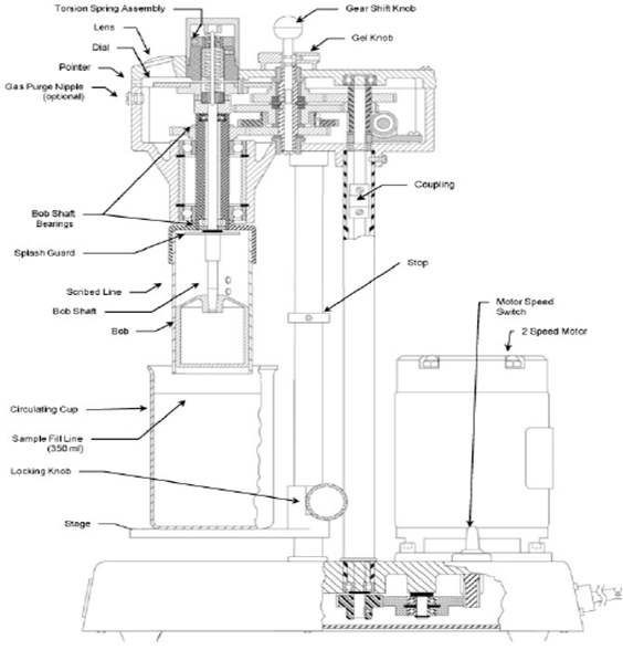
Table 2-1 VG35 Series Viscometer Specifications
| Model No. | Electrical | No. of speeds | Speeds |
| VG35-6 | 230 V, 50 Hz, 0.75 A | 6 | 600, 300, 200, 100, 6, 3 |
| VG35A-6 | 115 V, 60 Hz, 0.75 A | 6 | 600, 300, 200, 100, 6, 3 |
| VG35-12 | 230 V, 50 Hz, 0.75 A | 12 | 600, 300, 200, 180, 100, 90, 60, 30, 6, 3, 1.8, 0.9 |
| VG35A-12 | 115 V, 60 Hz, 0.75 A | 12 | 600, 300, 200, 180, 100, 90, 60, 30, 6, 3, 1.8, 0.9 |
 China
China